Trouver Système De Moteur Pas à Pas à Boucle Fermée Nema23 à 2 Phases, Moteur Pas à Pas De Boucle Fermée Par Prix Bas Pour Nema23 57Mm, 2 Servomoteur Hybride De Pas De Phase De Nema 23 De Boucle étroite Avec Le Conducteur dans le répertoire Industry, Reliable Fabricant / Fournisseur / Factory de Chine
nouveaux produits

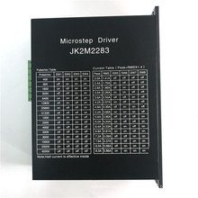

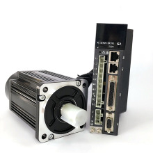
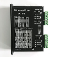
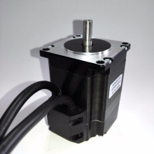
Modèle: JK57HS
 \ n \ n \ n
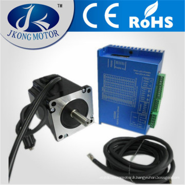
  \ n \ n \ n \ n Description du produit Caractéristiques: \ n 1.Fermeture boucle, élimine la perte de synchronisation \ n 2. Plage de fonctionnement plus large - couple plus élevé et vitesse plus élevée \ n 3.Réduction du chauffage du moteur et plus efficace \ n 4 .Smooth motion et super-faible bruit moteur \ n 5.N'a pas besoin d'une marge de couple élevée \ n 6.Non Tuning et toujours stable \ n 7.Réponse rapide, pas de retard et presque pas de temps de réglage \ n 8.High torque at démarrage et faible vitesse, rigidité élevée à l'arrêt. \ n 9.Prix moins élevé 10.20-50V, 8.0A Peak, Pas de réglage, Nulls perte de synchronisation \ n \ n Spécifications électriques (Tj = 25oC / 77oF) \ n \ n
 Parameters |
HBS57 |
|||
Min |
Typical |
Max |
Unit |
|
Output current |
0 |
- |
8.0 (Peak) |
A |
Input voltage |
20 |
36 |
50 |
VDC |
Logic signal current |
7 |
10 |
16 |
mA |
Pulse input frequency |
0 |
- |
200 |
kHz |
Isolation resistance |
500 |
|
|
MΩ |
Control Signal Connector - Screw Terminal |
|
||||||
Pin |
Name |
I/O |
Description |
|
|||
1 |
PUL+ |
I |
Pulse signal: In single pulse (pulse/direction) mode, this input represents pulse signal, each rising or falling edge active (software configurable, see hybrid servo software operational manual for more detail); In double pulse mode (software configurable), this input represents clockwise (CW) pulse, active both at high level and low level.4-5V when PUL-HIGH, 0-0.5V when PUL-LOW. For reliable response, pulse width should be longer than 10μs. Series connect resistors for current-limiting when +12V or +24V used. The same as DIR and ENA signal. |
|
|||
2 |
PUL- |
I |
|
||||
3 |
DIR+ |
I |
Direction Signal: In single-pulse mode, this signal has low/high voltage levels, representing two directions of motor rotation.In double-pulse mode (software configurable), this signal is counter-clock (CCW) pulse, active both at high level and low level.For reliable motion response, DIR signal should be ahead of PUL signal by 5μs at least. 4-5V when DIR-HIGH, 0-0.5V when DIR-LOW. Please note that rotation direction is also related to motor-driver wiring match. Exchanging the connection of two wires for a coil to the driver will reverse motion direction. The direction signal’s polarity is software configurable. |
|
|||
4 |
DIR- |
I |
|
||||
5 |
ENA+ |
I |
Enable signal: This signal is used for enabling/disabling the driver. In default, high level (NPN control signal) for enabling the driver and low level for disabling the driver. Usually left UNCONNECTED (ENABLED). Please note that PNP and Differential control signals are on the contrary, namely Low level for enabling. The active level of ENA signal is software configurable. |
|
|||
6 |
ENA- |
I |
|
||||
7 |
ALM+ |
O |
AlarmSignal: OC output signal,active when one of the following protection is activated: over-voltage, over current, short circuit and position following error. This port can sink or source 20mA current at 24V. In default, the resistance between ALM+ and ALM- is low impedance in normal operation and become high when HBS57 goes into error. The active level of alarm signal is software configurable. See Hybrid servo software operational manual for more detail. |
|
|||
8 |
ALM- |
O |
|
||||
Encoder Feedback Connector – DSub15 Female | |||||||
Pin |
Name |
I/O |
Description |
||||
1 |
EA+ |
I |
Encoder channel A+ input |
||||
2 |
EB+ |
I |
Encoder channel B+ input |
||||
3 |
EGD |
GND |
Signal ground |
||||
4 |
HW |
I |
Reserved |
||||
5 |
HU |
I |
Reserved |
||||
6 |
FG |
GND |
Ground terminal for shielded |
||||
7 |
EZ+ |
I |
Reserved |
||||
8 |
EZ- |
I |
Reserved |
||||
9 |
HV |
I |
Reserved |
||||
10 |
NC |
- |
Not Connected |
||||
11 |
EA- |
I |
Encoder channel A- input |
||||
12 |
EB- |
I |
Encoder channel B- input |
||||
13 |
VCC |
O |
+5V @ 100 mA max. |
||||
14 |
NC |
- |
Not Connected |
||||
15 |
NC |
- |
Not Connected |
||||
Power and Motor Connector- Screw Terminal | |||
Pin |
Name |
I/O |
Description |
1 |
U |
O |
Motor Phase U |
2 |
V |
O |
Motor Phase V- |
3 |
W |
O |
Motor Phase W |
4 |
+Vdc |
I |
Power Supply Input (Positive) 20-45VDC recommended, leaving rooms for voltage fluctuation and back-EMF. |
5 |
GND |
GND |
Power Ground (Negative) |
 \ n \ n \ n Exposition:
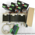
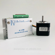
  \ N \ n \ n \ n \ n Nos Services \ n Nous ASLO alimentation Kits moteur Stepper, moteur pas à pas linéaire, moteur à courant continu, moteur pas à pas de freins, moteur Stepper avec encodeur, couplage flexible, Pully, Alimentation, SFE, etc. .. \ n \ n
Groupes de Produits : Fermer le moteur pas à pas de boucle > Moteur pas à pas NEMA23-57mm NEMA24-60mm